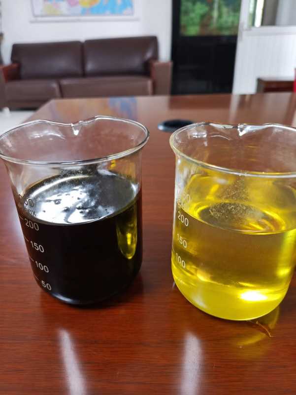
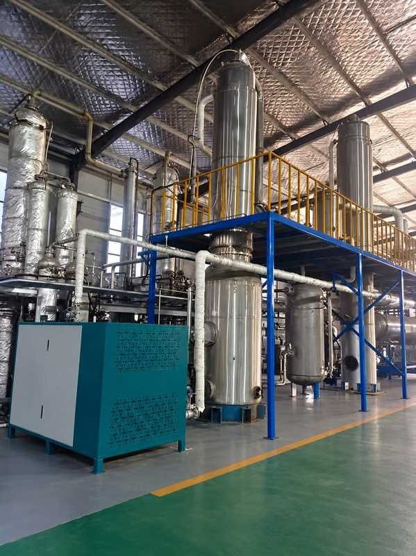
Waste Oil: Before / After Samples and Treatment Equipment
Process Flow
Equipment / System Architecture
What It Is
Waste-oil treatment removes free water, solids, light ends and selected contaminants so qualified material can be recovered as an industrial feed or sent to further rerefining. The route depends on oil origin, viscosity, additives, halogens, metals, water, fuel contamination and the legal/product status of the output.
Applications and Feedstock Boundaries
Potential feeds include segregated used lubricating oil, hydraulic oil and selected industrial oily streams. Transformer oil, fuel mixtures, PCB-risk material, emulsions and unknown waste require specific analysis and may need separate routes.
Main Equipment and System Architecture
Typical equipment includes sampling and unloading skids, segregated tanks and bunds, strainers/centrifuges, heaters and vacuum dehydration, filters or adsorption, condensers and off-gas treatment, pumps, laboratory instruments, fire protection and PLC batch controls.
The facility uses compatible contained tanks, hazardous-area electrical design, vapor control, grounding and dedicated lines to avoid mixing accepted product with unknown or off-spec oil.
Capacity and Design Basis
Capacity reflects delivery batches, oil viscosity, water and solids, heating/vacuum residence, laboratory release time, tank autonomy, residue production and dispatch schedule.
| Feed characterization | Analysis may cover water, sediment, viscosity, flash point, halogens, sulphur, metals, ash, fuel dilution, acidity and PCB screening where applicable. |
|---|---|
| Minimum / normal / peak basis | Receipt profile, operating hours, storage autonomy and the slowest processing or outlet interface are established from verified data. |
| Products and residues | Recovered oil requires an agreed use and batch specification; separated water and residues require written treatment or disposal criteria. Base-oil recovery is not assumed from simple dehydration. |
| Unverified values | Recovery, purity, yield, price, performance and disposal assumptions remain TBC until testing and outlet confirmation. |
Utilities and Infrastructure
Electricity, heating medium or fuel, cooling water, nitrogen or instrument air where required, bunded drainage, firewater/foam, ventilation, laboratory, loading roads and hazardous storage are included.
Required Customer Engineering Inputs
Customers provide source categories, volumes and batch profile, representative analyses, current handling, target product and buyer, residue routes, tank/site plan, utilities, fire code and emissions/discharge limits.
Automation, Monitoring and Quality Control
Batch authorization, valve line-up, tank level, temperature, vacuum, pressure and fire/gas alarms are interlocked. Laboratory release prevents cross-contamination and off-spec dispatch.
CAPEX and OPEX Drivers
CAPEX depends on storage segregation, heating/vacuum duty, purification depth, laboratory and fire/emissions systems. OPEX includes heat, power, filters/media, testing, tank cleaning, sludge/water treatment and rejected-load management.
Safety, Environmental and Compliance
Major hazards are flammable vapor, low flash-point contamination, static, hot oil, vacuum/pressure, tank entry, chemical exposure and incompatible unknown loads. Classification, grounding, ventilation, detection, bunding and emergency response are required.
Outputs and Acceptance Basis
Acceptance may cover batch receipt and traceability, dehydration/separation performance against agreed feed, product and residue tests, utility use, vapor/fire controls, alarms, documentation and training.
Implementation and Commissioning
The project proceeds through source inventory, laboratory screening, process trials, product/outlet confirmation, fire and hazard review, detailed tank/process design, FAT, construction, water/oil commissioning and controlled batch ramp-up.
Project Evidence
No verified completed-project claim or guaranteed recovery is attached to this page. Comparable evidence, if approved, will be identified during project evaluation. The process diagram is an engineering illustration, not a client-project photograph.
Frequently Asked Questions
Can all used oils be mixed together?
No. Source, chemistry, flash point, halogens, metals, PCB risk and target route determine segregation.
Does dehydration make base oil?
No. Removing water and solids can produce a recovered fuel or feed only if its specification and use are approved; rerefining requires additional processing.
Why test every load?
Unknown contamination can create fire, emissions, equipment and product risks and contaminate an entire tank.
How is PCB risk managed?
Suspect sources are quarantined and tested under applicable rules before acceptance or processing.
What happens to separated water?
It is characterized and treated in a suitable wastewater system; discharge is not assumed.
How are vapors controlled?
Closed transfer, controlled heating, condensation, ventilation and selected off-gas treatment are designed from composition and code.
Can off-spec oil be reprocessed?
Only if analysis shows a validated treatment route; otherwise it remains quarantined for an approved destination.
What data is needed first?
Source categories, representative batch analyses, volumes, target product, tank inventory, utilities and compliance requirements are essential.
Related Engineering Links
Waste Recycling & Resource Recovery Systems overview · Construction & Demolition Waste Recycling · E-waste Recycling · Projects & Cases · Request a Project Evaluation
Request a Project Evaluation
Provide quantity history, representative analyses or samples, contamination, site and utilities, target outputs, compliance limits and confirmed outlet constraints. Unknown information may remain TBC.
Preliminary Capacity & Technical Specification Range
| Typical configurable capacity | 5–200 t/day |
|---|---|
| Feed basis | Oil type, water, solids, additives, metals, viscosity, flash point and required recovered product |
| Typical outputs | Dehydrated/recovered oil or distillate fractions plus controlled water and residue |
| Key utilities | Power, thermal energy, cooling water, nitrogen/vacuum where required and vapor control |
Required for quotation: representative photos and samples, minimum/normal/peak feed quantity, composition and contamination analysis, operating hours, desired products and sizes, local emission/discharge limits, utilities, plot plan and required automation.
Request a Project Evaluation
Share representative waste characterization, throughput range, required outputs, utilities, site constraints and compliance requirements.
Start the engineering evaluation