
What it is
Utility upgrades must improve verified capacity, quality or reliability without creating new production constraints during cutover.
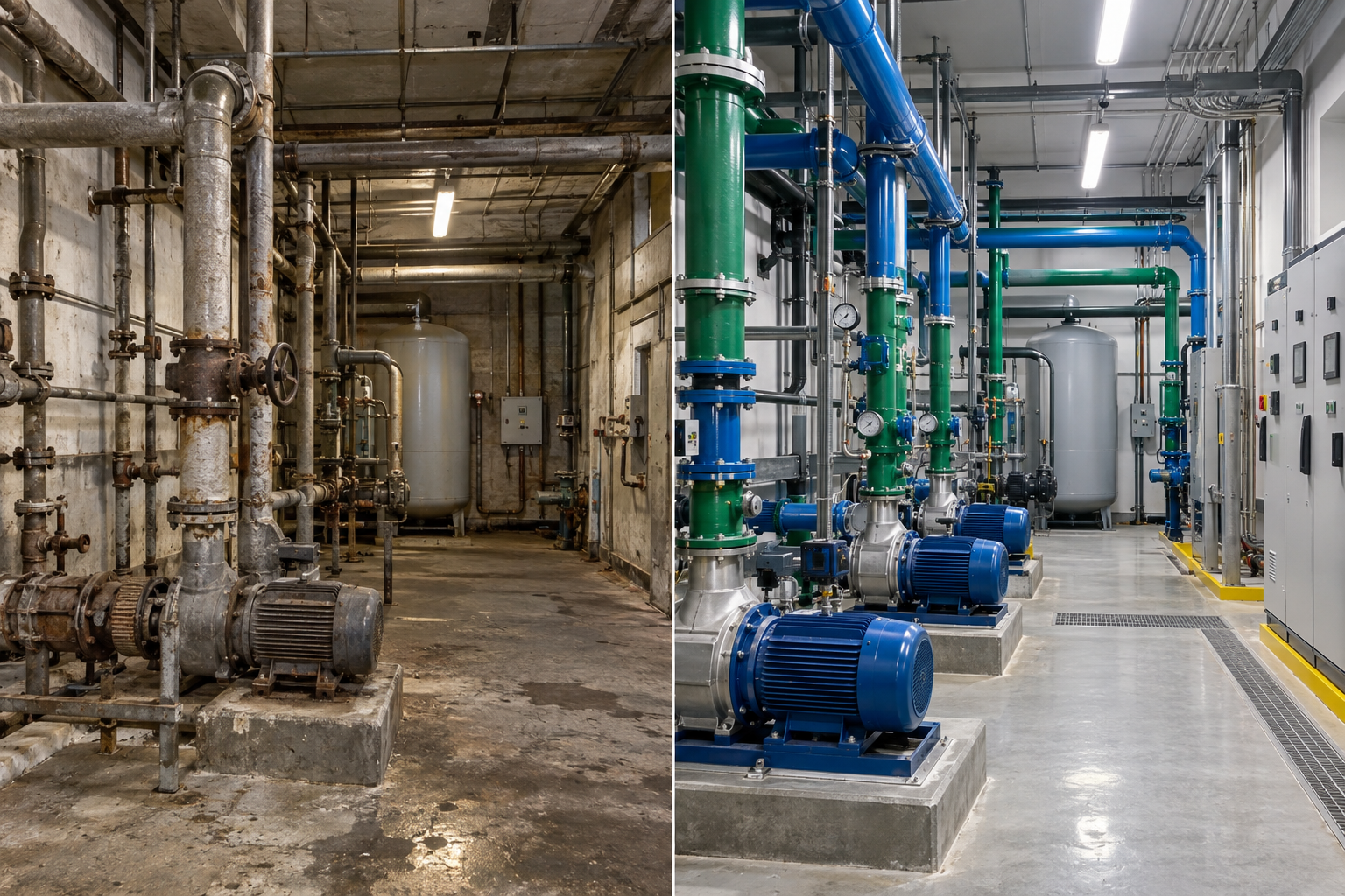
The project assesses generation, distribution and end-use conditions for power, compressed air, water, steam, cooling, refrigeration, gases or other defined services. It identifies retained capacity, losses, condition, redundancy and the modifications required for present and future production.
Typical applications
- Utility capacity expansion for production growth
- Replacement of unreliable or inefficient utility equipment
- Pressure, temperature or quality stabilization
- Distribution, metering and controls modernization
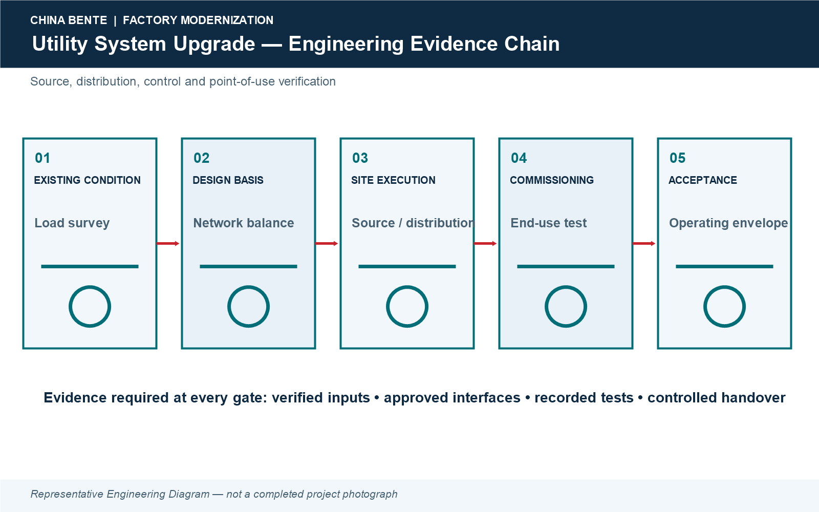
Representative sequence. Final outage, temporary-state and acceptance requirements are established from verified plant conditions.
Main equipment and system architecture
- Utility generation equipment within approved scope
- Headers, cables, pipes, valves and distribution
- Transformers, switchgear, pumps or compressors as relevant
- Treatment, filtration, drying or heat-exchange equipment
- Meters, PLC/SCADA and alarm systems
- Temporary services and isolation points
Capacity balance and design basis
Design uses measured low, normal and peak demands, required quality, pressure/temperature, coincidence, losses, redundancy, maintenance states and approved expansion. Connected load is not assumed to equal simultaneous demand.
Retained / replaced / interface matrix
| Category | Engineering basis |
|---|---|
| Retained | Serviceable sources and distribution proven to meet target capacity, quality, condition and compliance. |
| Replaced | Assets unable to meet verified duty, reliability, efficiency, supportability or safety requirements. |
| Interfaces | Production loads, tie-in points, controls, metering boundaries, drainage, heat rejection, emergency services and temporary states. |
Utilities and site infrastructure
- Incoming electrical, fuel and water capacity
- Plant-room and distribution space
- Drainage, blowdown and heat rejection
- Backup/emergency arrangements
- Future headers, feeders and metering points
Customer engineering inputs
- Utility measurements and production correlation
- Equipment lists, ratings and maintenance history
- Network drawings and field surveys
- Quality, pressure, temperature and availability needs
- Shutdown limits and expansion forecast
Quality, automation and control
Meters, controls and alarms are selected to maintain utility quality and reveal performance. Calibration and data boundaries are defined so acceptance is based on traceable measurements.
CAPEX and OPEX drivers
CAPEX includes source equipment, distribution, controls, civil works and temporary services. OPEX depends on demand, efficiency, leakage, fuel/energy, treatment, maintenance and operating strategy.
Safety, environmental and compliance
Pressure, electricity, hot services, chemicals, refrigerants, confined spaces, lifting, isolation and live-site work are addressed through approved procedures.
Outputs and acceptance basis
Acceptance includes capacity and quality tests, pressure/leak checks, balancing, redundancy where required, controls, documentation and training under agreed load conditions.
Shutdown, changeover and commissioning
Tie-ins are grouped into planned packages with temporary supply where justified, isolation checks, flushing/cleaning, energization and staged return to service.
Before / after evidence
No universal energy or reliability improvement is claimed. Approved utility before/after evidence is project-specific; see Projects & Cases.
Frequently asked questions
How is spare utility capacity verified?
By measured demand, source condition, distribution losses and required operating states.
Can upgrades be made without stopping production?
Some work can be staged, but tie-ins and testing require approved safe operating windows.
How is redundancy selected?
From production consequence, recovery time, maintenance and customer risk requirements.
Can existing headers be reused?
Only after size, condition, pressure, cleanliness and routing are verified.
Why is end-use measurement needed?
It separates source limitations, distribution losses and actual process demand.
What is included in balancing?
Flow, pressure, temperature or electrical loading is adjusted and verified across defined users.
How are temporary utilities managed?
They are engineered, protected, tested and removed under the approved cutover plan.
Can expansion be reserved?
Yes, with approved source margin, headers, feeders, controls and physical space.
Request a Project Evaluation
Share current records, measured constraints and the required future state. Any unverified baseline, benefit or acceptance value remains TBC.