Rooftop PV
Survey roof condition, structural reserve, wind loads, drainage, fire access and cable routes before fixing the module layout.
 CHINA BENTEINDUSTRY GROUP
Industrial solar PV EPC engineering based on verified load, solar resource, site, structural, grid and lifecycle requirements without fixed-yield claims.
FACTORY ROOFTOPS · INDUSTRIAL SELF-CONSUMPTION · O&M
Use the factory roof to generate electricity close to the production load. China Bente coordinates roof assessment, PV layout, mounting, electrical integration, optional storage and long-term maintenance. Ground-mounted stations and solar carports remain available as secondary applications.

Survey roof condition, structural reserve, wind loads, drainage, fire access and cable routes before fixing the module layout.
Match inverter output to the plant distribution board, transformer capacity, protection settings, metering and export permission.
Evaluate rail-guided or mobile cleaning equipment, dry or water-assisted cleaning, safe docking, remote supervision and roof access against the actual module layout and manufacturer requirements.
Ground-mounted PV stations and solar carports can be evaluated where the site requires them; the primary focus here is industrial rooftop generation.
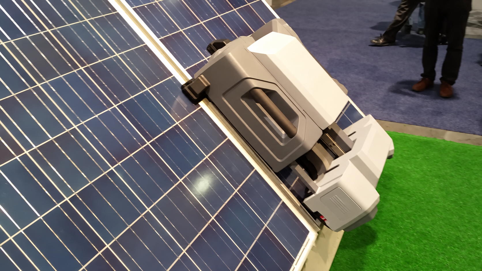
Plan maintenance while laying out the roof, not after installation. Robot movement, service paths, edge protection, docking and drainage must fit the actual array and the module manufacturer’s requirements.
Evaluate rail-guided and mobile systems for the roof geometry. Check row continuity, panel gaps, module surface compatibility, robot contact loads, allowable slope, turning and transfer points, edge sensing, wind limits, charging and safe recovery after a fault.
Match brushes and cleaning method to dust, soot, bird deposits and local conditions. Where water is used, define supply pressure, water quality, consumption, hoses and drainage; observe module instructions and avoid damaging the roof or electrical installation.
Trend inverter output, alarms and meter readings. Include soiling assessment and scheduled thermal-imaging or electrical inspections where appropriate, with investigation of abnormal strings, hot spots and insulation faults.
Provide access routes, fall protection, isolation points, lightning/earthing checks and roof-waterproofing inspections. Define operator roles, robot fault alerts, service logs, spare parts and the remote-access boundary.
| Parameter | Required project basis |
|---|---|
| Array geometry | Roof slope in degrees; row length and panel gaps in mm; obstacles and access routes. |
| Mechanical compatibility | Robot mass in kg, contact loading and module/frame limits; mounting-system and roof checks. |
| Cleaning duty | Surface area in m², acceptable cleaning window, soiling type and measured cleaning requirement. |
| Utilities and autonomy | Charging supply, battery duty, water quality/flow where used, communications and docking. |
| Safety and acceptance | Edge/fall protection, stop behavior, fault recovery, wind limits and witnessed trial cleaning. |
Equipment capability references: robotic cleaning and remote monitoring; water-assisted PV cleaning equipment. Final equipment selection is project-specific.
PV arrayPV inverterAC protectionFactory busGrid / meterMonitoringConcept architecture · final single-line diagram is project-specific
PV modules and mounting structures; string or central inverters; DC connectors and isolators; combiner equipment where required; AC boards; transformers where required; revenue and control meters; earthing, lightning protection and monitoring.
Map usable roof zones, skylights, smoke vents, drainage, obstructions, shading and service access. Review roof age, waterproofing, corrosion, structural reserve and local wind loads. Select mounting and cable routes without treating the gross roof area as usable PV area.
Check daytime production demand, existing transformers, distribution boards, cable routes, protection and metering. Define self-consumption and any export limit first. Batteries are optional: assess them only where the load, tariff or backup duty justifies storage.
Coordinate lifting, roof access, fall protection, shutdown windows, waterproofing interfaces and electrical isolation. Prepare method statements and inspections before energizing the completed installation.
Define monitoring, cleaning and robot maintenance, spare parts, alarm response, roof inspections and reporting. Handover includes layouts, single-line drawings, test records and safe operating instructions.
Rooftop capacity is established from verified usable area, fire and maintenance setbacks, structural capacity, module layout, shading, factory load, transformer capacity and grid rules—not from gross roof area alone.
| Parameter | Unit / basis | Engineering requirement |
|---|---|---|
| Roof survey | type, material, age, condition | Confirm roof zones, warranty, corrosion, waterproofing, drainage, skylights, vents and access. |
| Usable roof area | m² | Exclude setbacks, fire paths, shaded zones, fragile areas and equipment-maintenance corridors. |
| Structural basis | dead load, live load, wind uplift | Verify reserve capacity, anchorage or ballast, local wind/seismic conditions and reinforcement needs. |
| PV array rating | kWp / MWp DC | Select module quantity and rating from the verified layout; state temperature and shading assumptions. |
| Module schedule | Wp, Voc, Isc, dimensions | Confirm electrical characteristics, mechanical load rating, fire classification and approved module model. |
| String design | Vdc, A, modules/string | Check minimum/maximum temperature, inverter MPPT window, cable current and connector compatibility. |
| Inverter output | kW / MW AC | Define topology, continuous rating, voltage, reactive-power capability and thermal derating. |
| DC/AC ratio | project-specific | Optimize against climate, load shape, clipping, export restrictions and lifecycle economics. |
| Factory load profile | kW at agreed intervals | Use bills and interval data; identify weekends, shutdowns, minimum daytime demand and future loads. |
| Grid connection | V, Hz, fault level | Coordinate transformer, switchboard, protection, metering, harmonic and utility requirements. |
| Export control | kW import/export | Define meter location, permitted export, controller response and fail-safe behavior. |
| Yield model | kWh/year; kWh/kWp/year | Use site weather, orientation, shading, soiling, temperature, losses, availability and uncertainty. |
| Cable and protection | V, A, fault duty | Size DC/AC cables, isolators, surge protection, earthing, lightning and interface protection. |
| Fire and access | local code / insurer basis | Maintain fire lanes, roof access, emergency isolation, signage and firefighter coordination. |
| Monitoring / SCADA | signals, meters, alarms | Define inverter, weather, meter and robot data, alarm routing, reports and remote support. |
| Cleaning robot | roof/array-specific | Confirm row geometry, slope, gaps, obstacles, dry/wet method, docking, safety and rescue access. |
| Acceptance testing | approved test plan | Inspect mounting and waterproofing; test insulation, polarity, earthing, protection, meters, monitoring and utility witness items. |
Illustrative nameplate calculation: 1,000 modules × 550 Wp = 550 kWp DC. This is array rating, not a promise of 550 kW output at every hour. Annual generation requires a site-specific yield model.
Site location; interval electricity demand and bills; roof drawings or land survey; existing single-line diagram; transformer and switchboard ratings; export conditions; operating hours; access restrictions and local approval requirements.
CAPEX changes with mounting type, foundations or roof reinforcement, inverter arrangement, cable distance and grid works. OPEX includes inspection, cleaning, vegetation control where relevant, monitoring, spares and inverter lifecycle maintenance.
Approved layout and single-line diagram; structural verification; module/inverter schedules; cable and protection calculations; inspection and test records; meter/monitoring checks; utility authorization and handover documentation. Availability and energy guarantees, if requested, need an agreed weather-adjusted test basis.
Yes, after the roof condition, structural capacity, wind uplift, drainage, access and fire requirements are checked. Reinforcement or roof replacement may be a separate work package.
kWp is the PV module DC nameplate rating under standard test conditions. kW AC is the inverter or connection power rating. The two ratings are selected together but are not interchangeable.
Ordinary grid-following PV disconnects when the grid fails. Backup operation requires a separately engineered islanding arrangement, suitable grid-forming equipment, protection and load control.
Export-limiting control can be evaluated using a meter at the connection point and coordinated inverter control. The utility must accept the control arrangement and its response under changing loads.
Annual output is modelled from the solar resource, array orientation, shading, temperature, equipment losses and availability. A site yield study is needed before a generation commitment.
Often yes, but reserve physical space, electrical capacity, communications and a clear AC- or DC-coupled expansion concept during initial design.
The agreed plan covers mechanical inspection, electrical continuity and insulation, polarity, earthing, protection, inverter settings, meters, monitoring and utility witness tests where required.
Provide the site location, load and bills, roof or land information, distribution drawings, grid/export requirements and intended scope. Missing structural or grid information is identified before pricing.
Yes, as a defined maintenance-system scope after checking module compatibility, roof slope, row continuity, panel gaps, allowable loading, edge protection, docking and safe retrieval. Not every rooftop supports the same robot.
Select the method from the dust or residue, water availability and quality, module instructions, drainage and safe working conditions. Cleaning frequency follows measured soiling and the maintenance plan rather than a fixed universal schedule.
It can include inverter and meter monitoring, alarm handling, soiling assessment, inspection records, thermal-imaging surveys and work-order follow-up. Alerts require a defined operator response and safe access plan.
Share the site, load, grid interface and operating objective so the system can be engineered as a coordinated scope.