Peak-demand management
Discharge against an agreed demand target while maintaining the reserve and recharge opportunity needed for the next cycle.
 CHINA BENTEINDUSTRY GROUP
Industrial BESS engineering based on verified power, duration, usable energy, operating duty, degradation, grid and fire-safety requirements.
STORE · DISPATCH · PROTECT
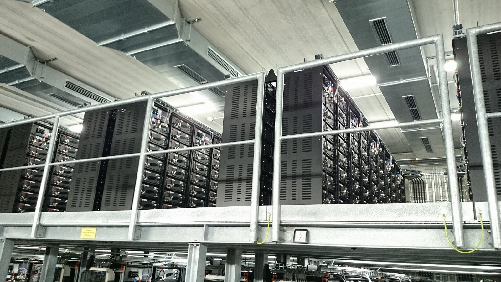
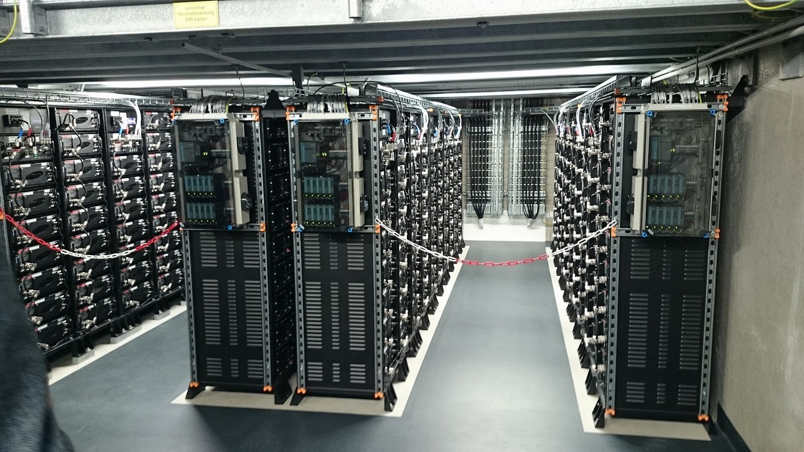
Specify battery storage by the job it must perform: peak management, renewable-energy shifting, controlled backup or power support. A complete BESS combines batteries, power conversion, thermal management, protection, controls and a defined connection to the plant.
Discharge against an agreed demand target while maintaining the reserve and recharge opportunity needed for the next cycle.
Charge from permitted grid or renewable sources, then discharge within tariff, export and battery operating constraints.
Define the essential-load board, transfer arrangement, starting demand and required runtime; do not treat a standard BESS as a UPS.
Coordinate cell monitoring, HVAC, detection, emergency shutdown, isolation, access and incident response with the selected system and local authority.
Battery / BMSPCS AC↔DCProtectionFactory busPCC meterEMS dispatchConcept architecture · final single-line diagram is project-specific
Battery cells, modules and racks; battery management system (BMS); bidirectional power conversion system (PCS); DC protection and isolation; HVAC or liquid cooling as selected; detection and fire-safety interfaces; transformer/switchgear; EMS, meters and communications.
Ratings and acceptance values are fixed in the project specification after the site and operating data are reviewed.
| Design parameter | Unit / basis | Engineering scope |
|---|---|---|
| Discharge / charge power | kW / MW AC | State continuous and permitted short-term power at the agreed boundary. |
| Nominal stored energy | kWh / MWh DC | Nameplate energy is not the same as energy delivered to the load. |
| Usable energy | kWh / MWh at defined boundary | State SOC limits, temperature, conversion losses, auxiliary consumption and beginning/end-of-life basis. |
| Discharge duration | hours | Delivered usable energy ÷ supported AC power, subject to operating limits. |
| Duty cycle | cycles/day; throughput | Define charge windows, discharge pattern, reserve and annual throughput. |
| Grid & plant interface | V; Hz; kVA | Check fault contribution, transformer rating, harmonics and protection coordination. |
| Operating environment | °C; humidity; elevation | Confirm derating, cooling duty, ingress/corrosion protection and clearances. |
| Lifecycle basis | Years; retained capacity | Agree the applicable warranty conditions, throughput limits and augmentation strategy. |
Illustrative duty: a constant 500 kW critical load for 2 hours needs 1,000 kWh delivered at the load boundary. Battery nameplate energy must additionally account for the permitted SOC window, losses, auxiliaries and the agreed aging margin.
Interval load and demand peaks; tariff and import/export terms; required backup loads and runtime; single-line diagram; available footprint; ambient conditions; fire authority requirements; intended cycle schedule and communications interfaces.
Battery energy and PCS power are separate cost drivers. Duration, redundancy, enclosure/cooling, fire-safety scope, transformer works and lifecycle augmentation change CAPEX. Losses, auxiliaries, maintenance and battery degradation affect operating cost.
Approved safety and protection design; battery/PCS documentation; factory tests; installation and communications checks; emergency-stop and alarm tests; measured charge/discharge performance at a defined meter; reserve/dispatch verification and operations training.
Power follows the maximum charge or discharge duty. Energy follows the duration and operating reserve. Evaluate the actual load trace rather than selecting MWh from the peak kW alone.
Not necessarily. The usable SOC window, conversion losses, auxiliaries, temperature and battery age affect delivered AC energy. State the measurement boundary and test conditions.
Only if the architecture and transfer performance meet the load requirement. A standard grid-connected BESS is not automatically a UPS; sensitive loads may need dedicated UPS equipment.
Chemistry is selected against the required duty, safety assessment, environment, warranty and available qualified equipment. It is confirmed in the project specification, not assumed from a generic page.
Review the selected equipment, separation distances, cooling, detection, shutdown, isolation, emergency access and incident plan against local requirements and authority approvals.
An AC-coupled retrofit may be practical, subject to switchboard capacity, grid permissions, protection, metering and control integration. DC coupling requires a compatible design.
Compare the warranted capacity, years, throughput, operating temperature, SOC limits and cycle conditions. Include replacement or augmentation allowances in the lifecycle evaluation.
Agree the AC/DC boundary, power, usable energy, SOC start/end, temperature, auxiliary accounting and acceptance tolerance before testing. Repeatability matters more than an isolated nameplate claim.
Share the site, load, grid interface and operating objective so the system can be engineered as a coordinated scope.