Daytime self-consumption
Supply factory loads from PV and decide when surplus should charge storage, export or be curtailed.
 CHINA BENTEINDUSTRY GROUP
Engineering for industrial solar and battery energy storage hybrid systems, using verified load, tariff, grid, site and operational resilience requirements.
GENERATE + STORE · COORDINATED OPERATION
Coordinate solar generation and battery dispatch as one operating system. The hybrid design balances daytime demand, stored energy, grid exchange and any agreed resilience duty instead of simply placing PV and a battery next to each other.
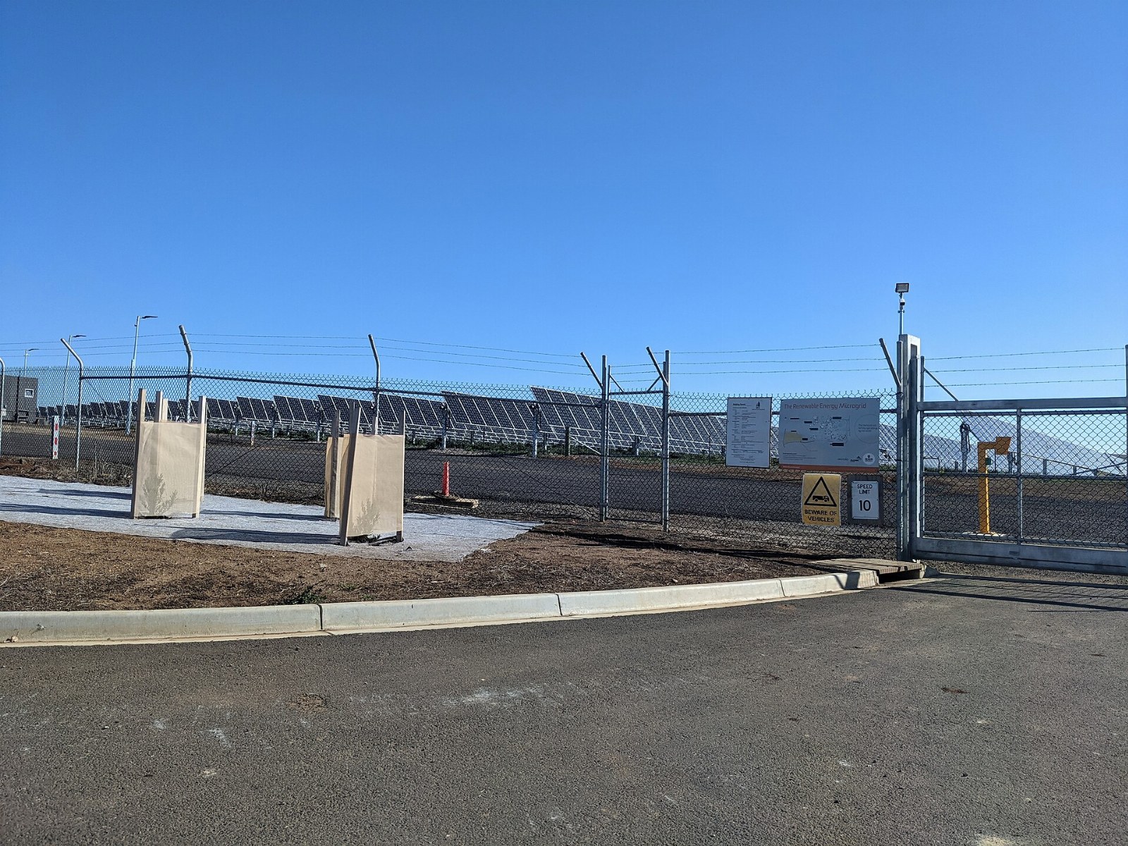
Supply factory loads from PV and decide when surplus should charge storage, export or be curtailed.
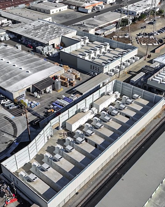
Discharge within the energy window and demand limit, allowing for tomorrow’s recharge and the battery reserve.
Where specified, provide a critical-load boundary, grid-forming source, isolation and load shedding; ordinary PV+BESS does not automatically provide backup.
Choose the coupling arrangement from existing equipment, voltage levels, conversion losses, expansion strategy and supplier compatibility.
Solar arrayPV inverterFactory AC busBESS + PCSGrid / PCCEMS controlAC-coupled concept · backup/islanding is a separate engineered scope
PV array and inverters; battery racks and BMS; bidirectional PCS; AC collection bus or compatible DC-coupled equipment; transformer and protection; point-of-connection meter; EMS; and, where backup is included, isolation/transfer equipment and critical-load distribution.
Ratings and acceptance values are fixed in the project specification after the site and operating data are reviewed.
| Design parameter | Unit / basis | Engineering scope |
|---|---|---|
| PV DC capacity | kWp / MWp | Derived from solar resource, available area, demand and export constraints. |
| Inverter / connection power | kW / MW AC | Coordinate PV output, BESS power, transformer loading and utility limits. |
| BESS power | kW / MW | Define charging and discharging duties separately from solar nameplate. |
| BESS usable energy | kWh / MWh | Match shift duration, reserve, aging allowance and permitted SOC window. |
| Import/export constraint | kW at connection meter | Set dispatch priority, curtailment policy and fail-safe behavior. |
| Backup duty, if included | kW; starting kVA; hours | Define critical loads, motor starts, transfer tolerance and recharge strategy. |
| Model resolution | Minutes or finer as required | Use sufficient detail to capture demand peaks, clouds, switching and tariff periods. |
Illustrative energy balance: 1,200 kWh of surplus PV does not imply that 1,200 kWh can be delivered later. Charge limits, storage headroom, conversion losses, auxiliaries and reserve reduce the usable shifted energy. Model each interval and the full duty cycle.
| Design parameter | Unit / basis | Engineering scope |
|---|---|---|
| Sunny production hours | PV → load → BESS | Export or curtail only under the agreed grid/dispatch rules. |
| Evening / peak period | BESS + grid → load | Discharge within usable SOC and retain any required backup reserve. |
| Grid failure | Only with engineered islanding | Isolate PCC; establish grid-forming supply; shed non-critical loads as designed. |
| Grid recovery | Controlled synchronization | Check voltage/frequency, reconnect under utility rules and restore loads in sequence. |
Interval load; site weather and shading; PV/roof information; existing PV details if any; tariff and export agreement; grid outage history; critical-load list; electrical drawings; space, safety and communication constraints.
Compare PV size, storage duration, coupling conversion stages, grid works and control scope together. Evaluate savings from the actual tariff and load model; no universal payback applies. Include battery replacement assumptions and operating reserve costs.
Issue the system single-line diagram, dispatch rules and mode-transition matrix. Commission meter polarity, PV/PCS communications, power limits, curtailment, battery reserves and fail-safe states. Test islanding and reconnection only when included in the agreed design.
No. Solar+BESS describes generation with storage. A microgrid additionally needs a defined electrical boundary and coordinated controls for its required grid-connected and islanded modes.
AC coupling connects PV and storage through an AC bus with their respective converters. DC coupling shares a compatible DC architecture. Retrofit constraints, voltage, losses and equipment compatibility determine the choice.
The controller follows the agreed export permission and dispatch rules. It may export permitted energy or reduce PV output when export and charging are unavailable.
Only if islanding, grid-forming capability, protection, critical-load transfer and load control have been engineered and commissioned. Ordinary grid-following PV and storage do not establish this automatically.
Yes, subject to generator limits, minimum loading, synchronization, protection, reverse-power prevention and coordinated dispatch. The generator control interface must be verified.
Define the order of self-consumption, peak management, backup reserve and tariff shifting. The EMS needs explicit conflict rules rather than competing independent settings.
Expansion can be planned through reserved space, switchboard and transformer headroom, compatible controls and an updated grid approval. Battery aging and mixed-generation compatibility must also be assessed.
Simulate the measured load, site PV output, tariff periods, export terms, battery losses, throughput and lifecycle costs. Any business case states its assumptions and sensitivities.
Share the site, load, grid interface and operating objective so the system can be engineered as a coordinated scope.