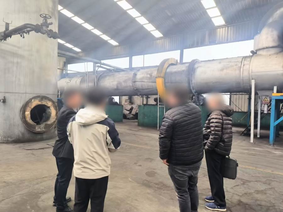
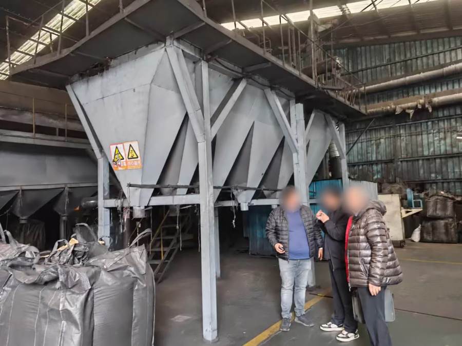
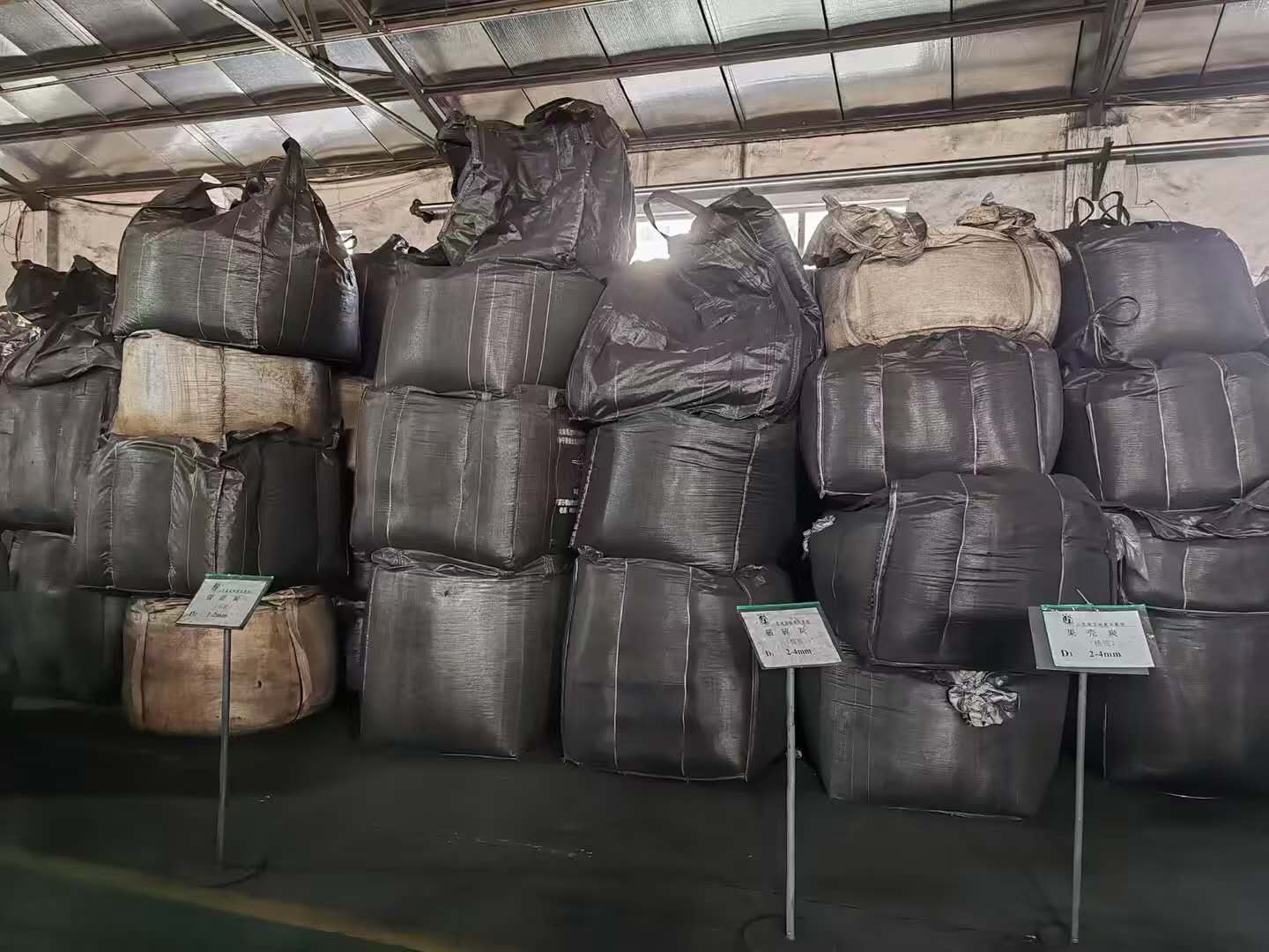
Indoor activated-carbon production with enclosed thermal processing and separate SMART warehousing and logistics interfaces.
What it is
A complete factory for suitable physical or chemical activation routes, with core production installed inside an enclosed industrial building.
Production-Line Capacity Options
The ranges below are preliminary selection bands, not guaranteed output. Final sizing depends on feedstock moisture and ash, carbonization/activation yield, residence time, product specification, operating hours and required redundancy.
| Line class | Finished product | Indicative hourly output | Typical configuration | Packaging |
|---|---|---|---|---|
| Compact line | 1–3 t/day | Approximately 0.05–0.15 t/h | Single feed-preparation train, one thermal-processing line, basic grading and dust collection | 20–25 kg bags; optional bulk bags |
| Standard industrial line | 3–10 t/day | Approximately 0.15–0.50 t/h | Continuous preparation, carbonization/activation, cooling, washing where required, grading and semi-automatic packing | 20–25 kg bags and 500–1,000 kg bulk bags |
| Large or parallel-line plant | 10–30 t/day | Approximately 0.50–1.50 t/h | Parallel or enlarged thermal lines, heat recovery, centralized off-gas treatment, automatic conveying, storage and packing | Automatic small-bag and bulk-bag systems |
Common Product Specification Envelope
| Feedstock | Coconut shell, wood/biomass, coal or other qualified carbonaceous material |
|---|---|
| Product forms | Powdered, granular or extruded/pellet activated carbon |
| Typical particle-size options | Powder approximately 100–325 mesh; granular commercial mesh grades; pellet approximately 0.9–4 mm |
| Indicative iodine-number selection | Approximately 600–1,200 mg/g, subject to raw material, activation route and verified test results |
| Automation | PLC/HMI standard; SCADA, traceability, remote monitoring and SMART warehouse interfaces optional |
Suitable feedstock / applications
Wood, biomass, coconut shell, coal-based or other carbonaceous feedstocks subject to proximate analysis, ash, moisture, contaminants and activation trials.
Process flow
Main equipment and systems
- Indoor carbonization and activation furnaces
- Feed, conveying and storage systems
- Washing, neutralization and dewatering
- Dryers, mills, screens and forming equipment
- Off-gas cleaning and waste-heat recovery
- SMART warehouse, AGV and PLC/SCADA interfaces
System and layout diagram
Design basis and required tests
Feedstock trials, iodine or applicable adsorption testing, ash, moisture, particle size, strength and contaminant analysis establish the design basis.
Utilities and infrastructure
Power distribution, water, steam or thermal energy, cooling, compressed air, industrial gases, drainage, fire protection, buildings, roads, storage and maintenance access are sized from the verified design basis.
Environmental integration
Indoor dust capture, furnace off-gas treatment, waste heat, wash water, residues, fire protection and explosion-risk controls are integrated. Relevant interfaces are coordinated with Turnkey Factory EPC · Waste Recycling · Difficult Wastewater · Renewable Energy · SMART Solutions.
CAPEX / OPEX drivers
Feed variability, process route, throughput, materials of construction, energy demand, emissions limits, automation, redundancy, local construction, logistics and product acceptance criteria drive lifecycle cost.
Outputs and acceptance basis
Powdered, granular or extruded carbon is accepted against agreed sampling and adsorption, ash, moisture and size methods. No capacity, yield, quality or certification is assumed until supported by testing and an agreed design basis.
Customer engineering inputs
Representative samples and analyses, target products, operating schedule, site survey, climate, utility data, applicable codes, discharge limits, plot plan, logistics and acceptance protocol.
Delivery scope
Concept definition, feasibility, process and layout engineering, equipment selection, procurement, civil and construction interfaces, utilities, automation, environmental systems, installation support, FAT/SAT, commissioning, training, trial operation and lifecycle service can be included within the agreed boundary.
Frequently asked questions
What information is required to evaluate Activated Carbon Manufacturing Plant EPC?
Provide feedstock or product data, target throughput, operating hours, site conditions, utilities, local regulations, output specifications and available laboratory results.
Is one process route suitable for every project?
No. The route is selected from verified material characteristics, product requirements, environmental limits, local infrastructure and lifecycle economics.
How are capacity and equipment sizes confirmed?
They are established through a documented design basis, representative testing where needed, mass and energy balances, availability assumptions and agreed design margins.
Which utilities must be defined?
Electrical supply, process water, steam or heat, cooling, compressed air, industrial gases, drainage and clean utilities are confirmed for the selected process.
How are environmental systems integrated?
Wastewater, exhaust gas, dust, odour, residues, noise, heat recovery and water reuse are designed alongside the process rather than added after equipment selection.
Can automation be included?
Yes. PLC, HMI, SCADA, instrumentation, interlocks, traceability and optional MES interfaces are developed to the agreed operating philosophy.
What does acceptance cover?
Acceptance boundaries can include document review, FAT, installation checks, SAT, commissioning support, training and performance verification against agreed inputs and test methods.
How are CAPEX and OPEX controlled?
Major drivers are route complexity, materials of construction, utility demand, emissions controls, automation level, local construction, logistics, redundancy and output specification.